
Cellular DAS
Supports distributed cellular coverage inside facilities. Carrier-connected systems depend on carrier participation and authorization, and on a qualified RF design.

Distributed Antenna Systems (DAS)
Modern commercial facilities increasingly depend on reliable wireless connectivity across large, complex, and signal-challenging environments. Texas Low Voltage Communications supports Distributed Antenna System infrastructure and deployment for commercial and enterprise projects with disciplined coordination, structured pathways, cabling, antenna infrastructure, testing support, and documentation.
In-building wireless infrastructure
In-building wireless infrastructure and coverage solutions for commercial and enterprise environments, including DAS pathways, cabling, antenna infrastructure, equipment coordination, testing support, and deployment.
Compliance qualifier
Public-safety/ERCES and carrier-connected systems are subject to project requirements, applicable licensing, AHJ approval, frequency-holder/carrier authorization, and qualified design requirements.
Fundamentals
A Distributed Antenna System (DAS) distributes wireless signal throughout a building or facility using strategically placed antennas connected to centralized equipment, often called the head-end.
Signal from a source, such as a carrier connection or a public-safety radio source, is carried over fiber and coaxial cabling to antennas across floors, risers, and hard-to-reach spaces. Concrete, steel, low-E glass, and below-grade areas can weaken outdoor signal. A DAS is designed to help bring coverage to those areas.
Systems may be passive (signal sent over coax and splitters) or active (signal converted for fiber transport to powered remote units). The right approach is set by a qualified RF design.
Where DAS is used
Possible applications where in-building wireless infrastructure is commonly considered. These are typical DAS environments, not a list of completed TLVC projects.
DAS infrastructure capabilities
TLVC installs and coordinates DAS infrastructure for passive DAS and supports active DAS deployments. We work to the approved design from the responsible RF designer or integrator.
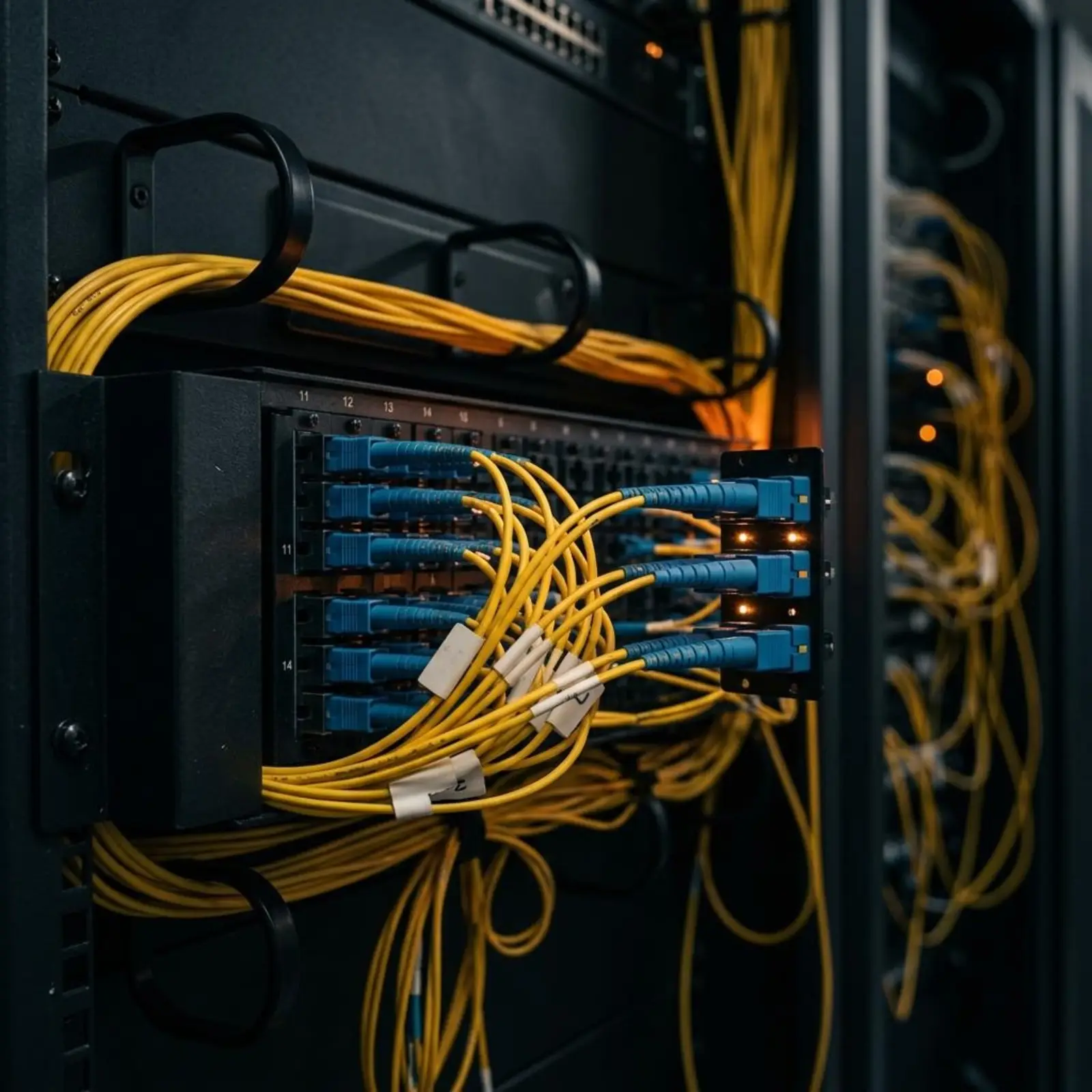
Pathway planning & coordination
Routes, sleeves, and pathway coordinated with drawings and other trades.
Fiber infrastructure
Backbone fiber between head-end, remote units, and distribution points.
Coaxial infrastructure
Coax distribution runs installed to the approved design.
Antenna cabling
Cabling to antenna locations defined by the responsible designer.
Antenna mounting
Mounting infrastructure installed at approved antenna positions.
Riser infrastructure
Vertical pathways and riser runs between floors and equipment rooms.
Equipment-room coordination
Head-end and equipment-room space, power interfaces, and layout coordination.
Cable management
Supported, organized, and serviceable cable runs.
Labeling
Consistent identification of cables, antennas, and terminations.
Testing support
Infrastructure testing and support for system-level testing by responsible parties.
Documentation
Records of installed infrastructure retained with the project file.
Closeout support
Punch completion and closeout records for the owner and GC.
Potential scope

Types of DAS
An overview for planning only. TLVC does not claim independent authority to design, certify, commission, or operate regulated public-safety/ERCES or carrier-connected systems.
Supports distributed cellular coverage inside facilities. Carrier-connected systems depend on carrier participation and authorization, and on a qualified RF design.
Emergency responder radio communication systems support radio coverage for first responders where required by the AHJ or applicable code.
Public Safety / ERCES systems may require AHJ approval, frequency-holder authorization, qualified design, licensed or certified personnel, and testing and acceptance. TLVC's role is set per project and does not include certifying ERCES compliance. Fire alarm is not part of TLVC's DAS offering.
May support dedicated or enterprise wireless environments, depending on project requirements. Not every enterprise wireless design is a DAS. Many use Wi-Fi or other architectures instead.
Scope dependencies
Final DAS scope is project-specific and may depend on RF design, carrier requirements, AHJ requirements, frequency-holder authorization, applicable licensing, system certification, and qualified engineering/design responsibilities.
How TLVC supports DAS projects
The TLVC operating model, applied to in-building wireless infrastructure.
Confirm facility requirements, drawings, RF/design responsibilities, stakeholders, schedule, and project constraints.
Coordinate pathways, cabling, equipment locations, antenna infrastructure, vendor requirements, RF-design inputs, and project interfaces.
Install approved infrastructure, coordinate field activities, support system deployment, manage changes, and maintain project documentation.
Support testing, documentation, punch completion, closeout records, and coordination with responsible system designers, integrators, carriers, or AHJs where applicable.
Who we work with
TLVC is positioned to work with the roles below. These are project roles, not formal partnerships.

Owners, GCs, facility & enterprise teams
Start a sales conversation, or send plans and bid documents to estimating. Both routes arrive with DAS already selected.